Last Updated on March 16, 2024

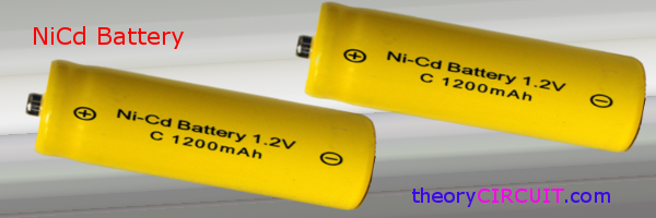
We may use AA or AAA size batteries in different applications and appliances, we can replace and cut costs on those batteries by Ni-Cd batteries. Yes it is rechargeable and can be used in traditional way, As we know nickel cadmium battery termed as Ni–Cd battery or NiCad battery in those nickel oxide hydroxide and metallic cadmium used as electrodes.
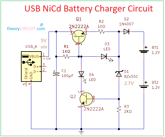
Here USB powered NiCd Battery Charger circuit designed by using few easily available components. The input power source of this charger circuit is 5V 1A from the USB-A port and the charging output is 1.2V 120mA which can be easily charged to the battery. Here two batteries are connected in series.
Circuit Diagram
BOM
| S NO | Designator | Value | Quantity |
| 1 | USB-A | 1 | |
| 2 | Transistor | 2N2222 | 2 |
| 3 | D1 Zenerdiode | BZx55C | 1 |
| D2 | 1N4007 | 1 | |
| D3,D4 | LED | 2 | |
| 4 | R1 | 1kΩ | 1 |
| R2 | 10Ω | 1 | |
| R3 | 2KΩ | 1 | |
| 5 | C | 100μF | 1 |
Construction and Working
To Construct this circuit you can use either USB A Receptacle or USB A cable Make sure not to short circuit D+ and D- lines. VBus (+5V) and Gnd lines will be used as input power source to this circuit and Capacitor C1 acts as filter element. Q1 transistor acts as current limiting element and provides up to 120mA current at output through reverse voltage protection diode D2. Here LED D3 (use any color as you want) indicates the Charging. Zener Diode D1 Regulates the voltage to 2.7V, Whenever the batteries are full then VBE of Q2 changes and makes Q2 Turn ON So the voltage to the base of Q1 ground through Q2 transistor this will make LED D4 Glow and LED D3 OFF. You can change the Sensitivity level of full charge or over charge by adding Variable Resistor instead of R3.
This circuit is designed to charge only two NiCd batteries with 1200mA current ratings, if you are using more than two or NiCd battery pack then you have to modify the charger circuit elements based on you target battery ratings.


D3 is not working as it may not getting proper voltage difference to get it ON during battery charging,
Battery charging voltage is received correctly, also D4 is working but with reverse polarity, I checked circuit connection many time with above arrangement but no clue.
Hi coolAwi
Check the transistor (2N2222A) Q1 and Q2 and its terminals. and also the USB power supply pins.
Hello sir
Thanks for this good circuit. How can I increase charging current of the batteries to more than 120 mA considering the maximum collector current of 2N2222a is 800mA? What is you comment in this regard?
Best regards
How many volts should the 100 uf capacitor be?
10V to 16V