Last Updated on October 26, 2024
A Light to Frequency Converter Circuit used in many electronics applications and measurement tools. This type of conversion allows us to get output more accurate in broad scale., Optical Encoders, Ambient light sensing and Proximity sensing are the best examples for Light to Frequency converter application. Even though specialized and dedicated elements like TSL237, TSL235R and S9705 available in the market, for experimenting and simple applications we can build our own. This DIY Light to Frequency Converter Circuit Using IC 555 made with commonly available components like LDR (5mm), Resistor and few disc capacitors. You can directly use it to control output actuators (by Voltage change) or it can be easily interfaced with Microcontrollers, Arduino or ESP32 Boards. PCB Gerber files for this circuit also given here, let’s jump into prototyping.
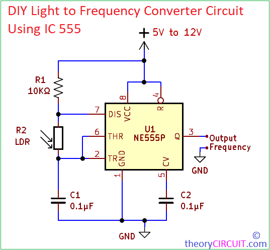
Output frequency from this circuit is depends on the light intensity falls on LDR (Light Dependent Resistor). This circuit constructed as a Astable Multivibrator, so that it can continuously oscillate square wave output depends on the timing element R1, R2 and C1. Here we used LDR for R2. So the Resistance value of LDR changes in according to light intensity. It may change from few hundred ohms to few Kilo Ohms. For average calculation we assume its Resistance as 6KΩ in room light condition, and so you can calculate the average output frequency from Astable Multivibrator calculator.
Circuit Diagram
Components Required
| 1 | C1, C2 | 0.1µF | C_Disc_D3.0mm_W2.0mm_P2.50mm | 2 | ||
| 2 | R1 | 10KΩ | R_Axial_DIN0207_L6.3mm_D2.5mm_P10.16mm_Horizontal | 1 | ||
| 3 | R2 | LDR | TestPoint_2Pads_Pitch5.08mm_Drill1.3mm | 1 | ||
| 4 | U1 | NE555P | DIP-8_W7.62mm | 1 | ||
| 5 | J1, J2 | Screw_Terminal_01x02 | TerminalBlock_bornier-2_P5.08mm | 2 |
Working Video
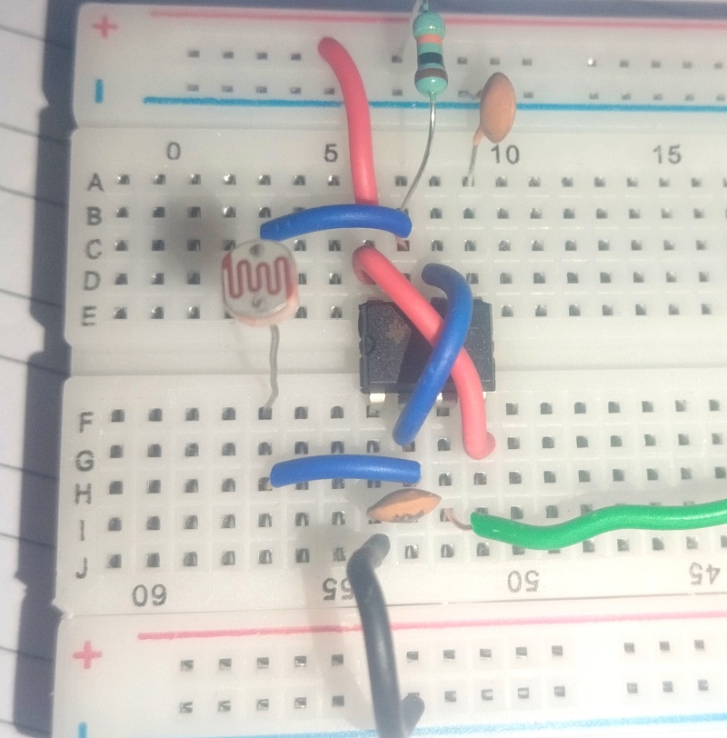
Construction & Working
Construction of this circuit is as simple as building Astable multivibrator, When there is changes in light intensity then the value of R2 also gets change.
- Light Intensity ↑ – LDR Resistance ↓
- Light Intensity ↓ – LDR Resistance ↑
By this act Timer IC 555 oscillates different frequency output. You can give power supply from 5V to 12V for this circuit operation.
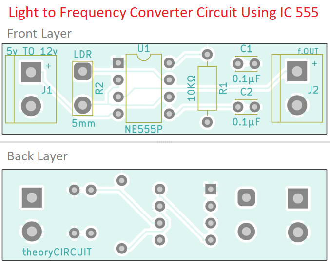
Printed Circuit Board
Download DIY Light to Frequency Converter Circuit Using IC 555 PCB Gerber Files here.
Interactive Board Viewer


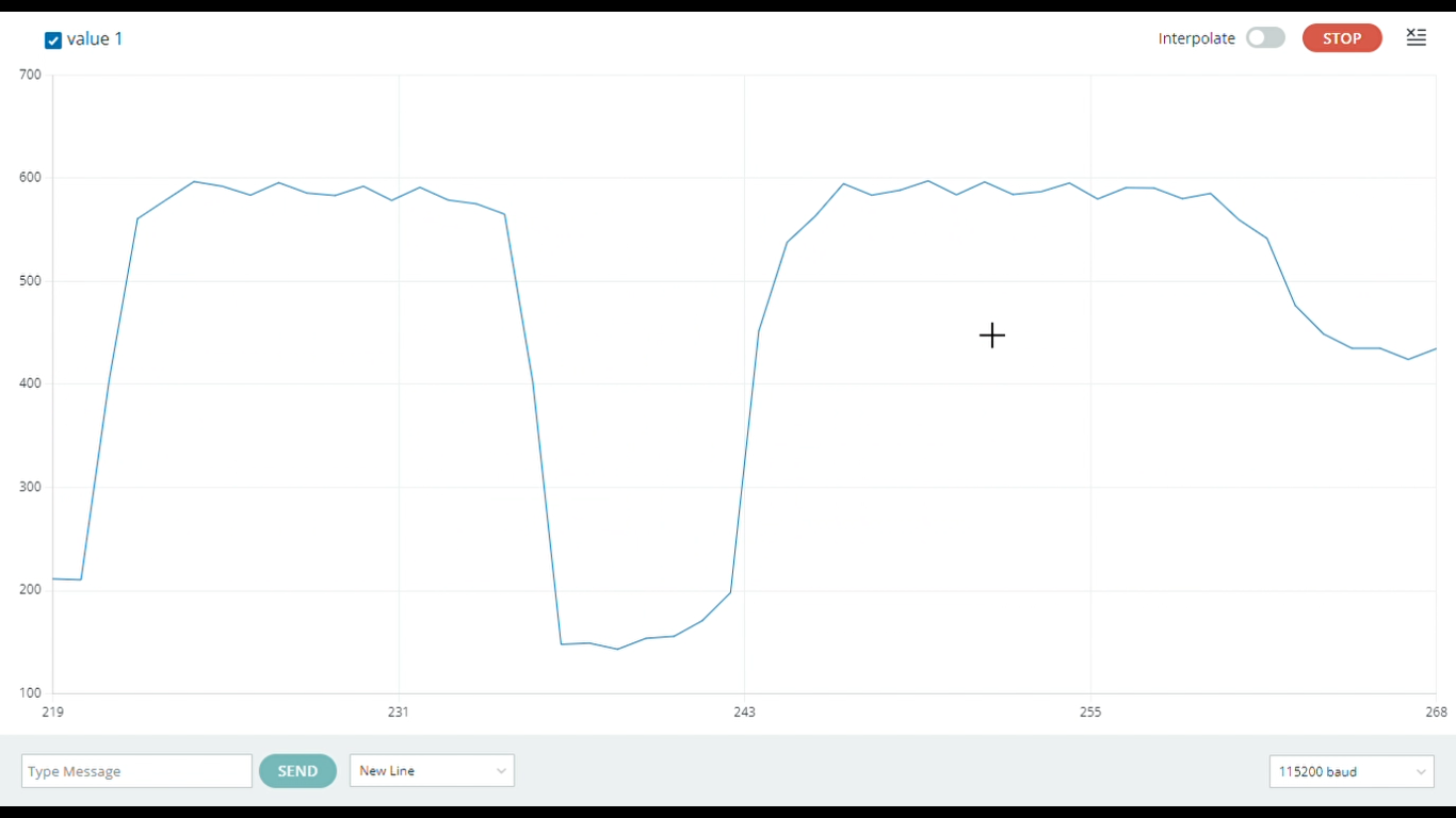
To plot the frequency wave, i have used ESP32 (DOIT Devkit V1) board and connected output from 555 IC to GPIO15 and Gnd to Gnd. Here is the Arduino Code for visualizing frequency changes depends on light intensity.
//Code by theoryCIRCUIT for frequency measurement using ESP32
const int inputPin = 15; // Pin where the frequency signal is connected
unsigned long duration;  // Variable to store the pulse duration
float frequency;         // Variable to store the calculated frequency

void setup() {
    Serial.begin(115200); // Start serial communication at 115200 baud
    pinMode(inputPin, INPUT); // Set the input pin mode
}

void loop() {
    // Measure the HIGH and LOW duration of the pulse
    unsigned long highDuration = pulseIn(inputPin, HIGH);
    unsigned long lowDuration = pulseIn(inputPin, LOW);

    // Calculate total period duration
    duration = highDuration + lowDuration;

    if (duration > 0) {
        // Calculate frequency in Hz
        frequency = 1.0 / (duration * 1e-6); // Convert microseconds to seconds
        Serial.println(frequency); // Print frequency to Serial Monitor
    } else {
        Serial.println("0"); // If no pulse detected, print 0
    }

    delay(100); // Small delay to control the update rate
}
Screenshot