Last Updated on March 16, 2024
Touch switch have tons of applications in real world, To design a robust One Touch to ON-OFF Switch you don’t need to depend on Expensive microcontrollers or Capacitive touch sensors, here Simple one touch to ON and one touch to OFF switch circuit is designed by using most famous Timer IC 555. You can construct this circuit within few minutes if have all the components in your hand and it is joy to experiment. This circuit can be used to control lights, appliances, or other devices with a simple touch.
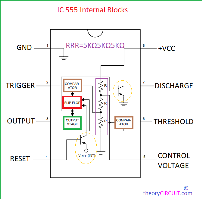
Here two differ circuit given ( B-) really), One circuit is to turn on/off the single LED with touch input and another circuit is to control lights, appliances, other devices through Relay. In these circuits we don’t need to oscillate pulse so there is no connection in Discharge pin (7) of timer IC 555. They are configure to toggle output state either HIGH or LOW depends on Touch input. Here Four copper strip is used as Touch plate. For ON and OFF touch, Place two plates within 2mm gap and the purpose is to make contact between plate when we touch with finger.
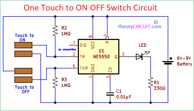
Circuit Diagram
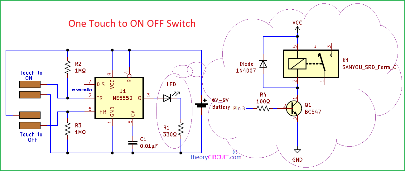
Circuit With Relay
Components
| S.No | Name | Quantity |
| 1. | IC 555 | 1 |
| 2. | LED | 1 |
| 3. | Resistor 1MΩ, Resistor 330Ω | 2, 1 |
| 4. | Capacitor 0.01uF | 1 |
| 5. | Small metal piece (for touch switch) – Copper strip | 4 |
To construct circuit with relay you need these additional components
- Relay – sanyou srd relay SPST 6V
- Transistor BC547 NPN
- Diode 1N4007
- Resistor 100Ω
Construction & Working
Output section only have the changes for LED and Relay based One Touch to ON-OFF Switch, other parts are same. Here we have to connect copper strips to ensure flow of Negative to Trigger input pin (2) and Positive to Threshold pin (6) when we touch with our finger.
During the Initial State or idle state the timer is stable in its state (either ON or OFF), During the touch of ON copper strips Negative supply (small value) flows through our skin and reaches the trigger input pin and falling edge detected by the internal comparator and flip flop then flip flop goes to Set condition hence the output will be HIGH that is ON condition. During the touch of OFF copper strips Positive supply (small Value) flows through our skin and reaches the Threshold pin and internal comparator then output of comparator reach Reset pin of Internal SR flip flop and makes the output state to LOW that is OFF condition.
At the output pin 3 we can connect either LED or Relay to control with one touch.
Timer IC 555 Pinout
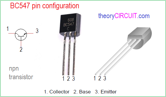
Transistor BC547 Pinout