Last Updated on March 16, 2024
Smartphone, Smartwatch, Bluetooth device and Battery powered devices are become an indispensable part of our lives. To keep those devices alive we need to charge when it requires. The Power banks are additional power source and it ensures the power backups when we travel or in emergency situations. This Article will help you to design a Portable cost effective Power Bank Circuit for Smartphones with variable DC output, hence you can change the output voltage range depends on your phone battery specification.
Even though it is Named as power bank for smartphones, it can be used for many battery powered devices for emergency charging. Keep in mind that you have to precheck the output voltage level of this circuit and your target device charging voltage and current ratings before connecting it for charging.
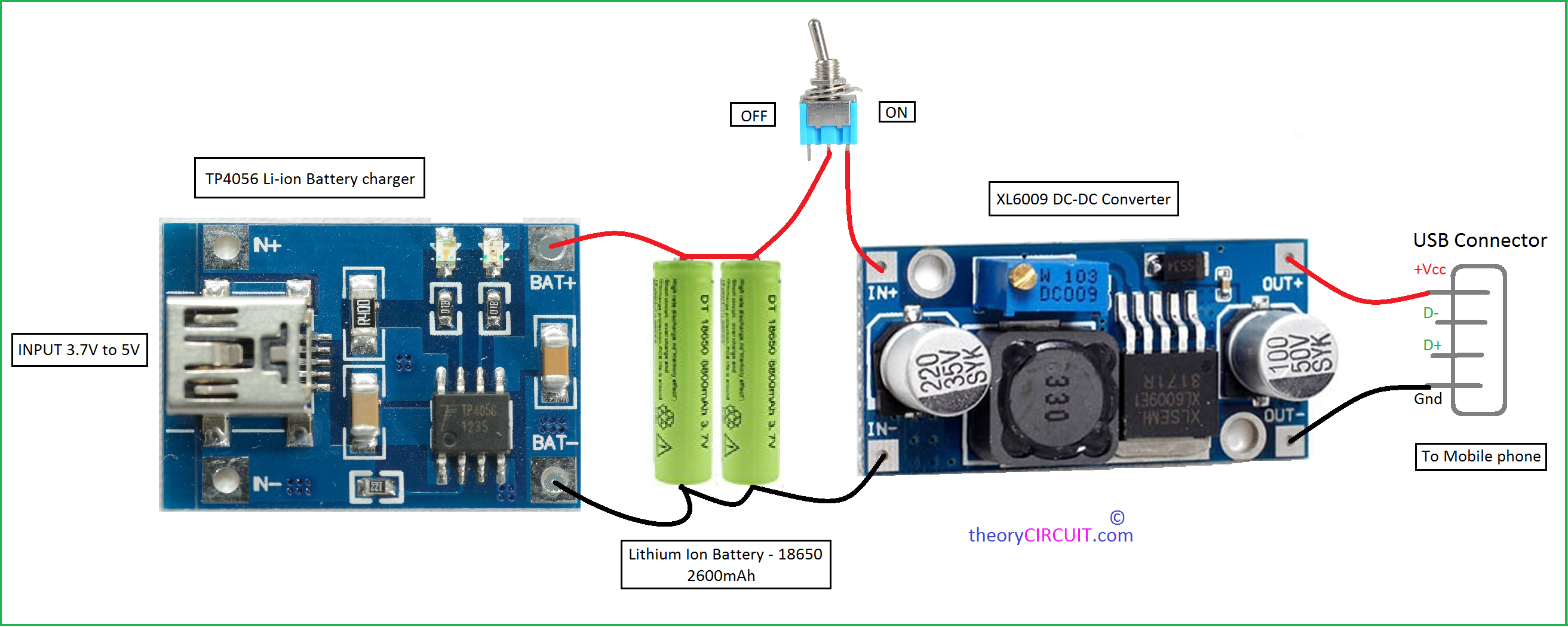
Power Bank Modules connection diagram
Power Bank Circuit Operation
It contains Three stages, first one is TP4056 Li-ion Battery charger module, input power supply to this board is from 3.7V to 5V and gives output to the battery the second stage.
Here 18650 Lithium-ion battery 2600mAh is used (solder the same polarity in parallel as shown in image), If you need then you can connect ON/OFF toggle switch. Third stage is XL6009 DC-DC converter this board drives the battery supply to USB connector (class A female) here the mobile phone is connected for charging . Vary the Trimpot in DC-DC converter board to get proper range output voltage.
“Check the Output Voltage and Current range before connecting the smartphone, Excessive or Reverse Polarity could Dangerous to your mobile battery.”
Power bank Circuit Diagram
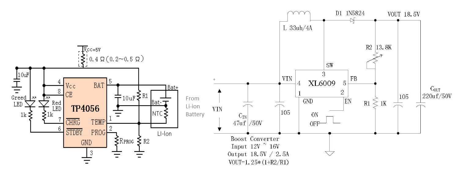
Circuit diagram of power bank given in two segments here the first one is Li-ion battery charger and second one is XL6009 DC-DC converter. It is given for reference and these are available in breakout board widely.
why no connection at d- d+ pin of usb connector?
Yes there is no connection at D+ D- pin of USB connector! because they are twisted pair wires responsible for carrying a differential data signal and they are no need for charge your mobile phone.
They are data transmitters
Would that circuit not discharge the 18650 batteries too much and damage them?
The TP4056 has over discharge protection so over discharge shouldn’t be a problem provided the charger has that mine looks a little different.
Heat sink is required or not in step up UpTo 12 v
Second question how can I messed out put amp. With multimeter
I have rechargeable battery about 4.5v with the circuit of charging charging circuit from 230v ac. Is it possible to make power bank?
How many battery has been connected to make around 5000mAh. And give me a circuit diagram for this
Do you have a circuit diagram for a boost chip which can boost 3v to 5v with 1-2A output
What is the USB output votage and curren and we can adjest that ?
if i use 18650 8800mAh 3.7V li-ion …is there any problem ?
if i use 18650 8800mAH Li cell…is there any problem?
I would not recommend using the cheap Chinese version of XL6009, it is extremely unreliable and inefficient, most of your Li-ion pack’s energy will be wasted as heat, not to mention the voltage fluctuations, and voltage spikes when automatic shutdown of the XL6009 will be activated, which will force you to put a proper heat sink and that will make it impractical as portable power bank. This boost convertor is also known to leak current slowly without a load, which will drain your battery pack fast. Try high efficiency boost convertor chips like LTC3769, LTC3872, MAX668, there are plenty out there, and building a boost convertor circuit isn’t rocket science either, internet is full of details, calculators, data sheets to help you calculate component values. The MT3608 boost convertor is a great candidate for your power bank circuit since it has a voltage input as minimum as 2 volt and it has a frequency switching as high as 1.2 MHz, with a maximum output current of 2 Amps, it should be more than enough for your power bank project.
That scheme I did had damaged tp4056 completely.