Last Updated on May 5, 2024
Inverter Circuits are very helpful during the power cuts and for portable power source. If the load connected to the inverter circuit is very small means we don’t need pure sine wave inverter or bulk inverter with high power. Simple Inverter Circuit using IC 555 designed with few easily available components.
We can create simple small inverter circuit to handle low power devices. The Timer IC 555 Oscillates high frequency square pulse and the Transformer step up the pulse into High AC Voltage.
This circuit involves in handling of High AC Voltage at output that can be lethal, Handle with extreme care.
Inverter Circuit using IC 555
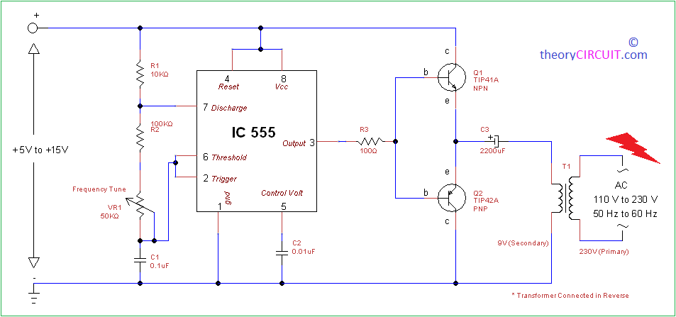
Construction & Working
The timer IC555 is used as a switching pulse oscillator and it is the main part in this circuit, IC 555 configured as Astable Multivibrator to give continuous switching pulse, two switching transistors TIP41A (NPN) and TIP42A (PNP) drives the transformer T1 according to the pulse input at the base. The transformer T1 is 230V primary to 9V secondary but connected in reverse, So it can react as step up transformer. We can apply +5V to +15V DC bias to this circuit and get 110V to 230V AC with 50Hz to 60Hz frequency but output may not pure sine wave as the PWM inverter output, it gives only pulsated AC.
The output frequency of this circuit can be varied by varying VR1 resistor.
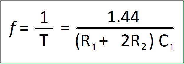
Use this formula to calculate the output AC supply and frequency, here R2 = R2+VR1 from given circuit. Use heat sink for Transistors to avoid over heat, Use 1 A to 1.5A transformer.
How Switching Inverter works?
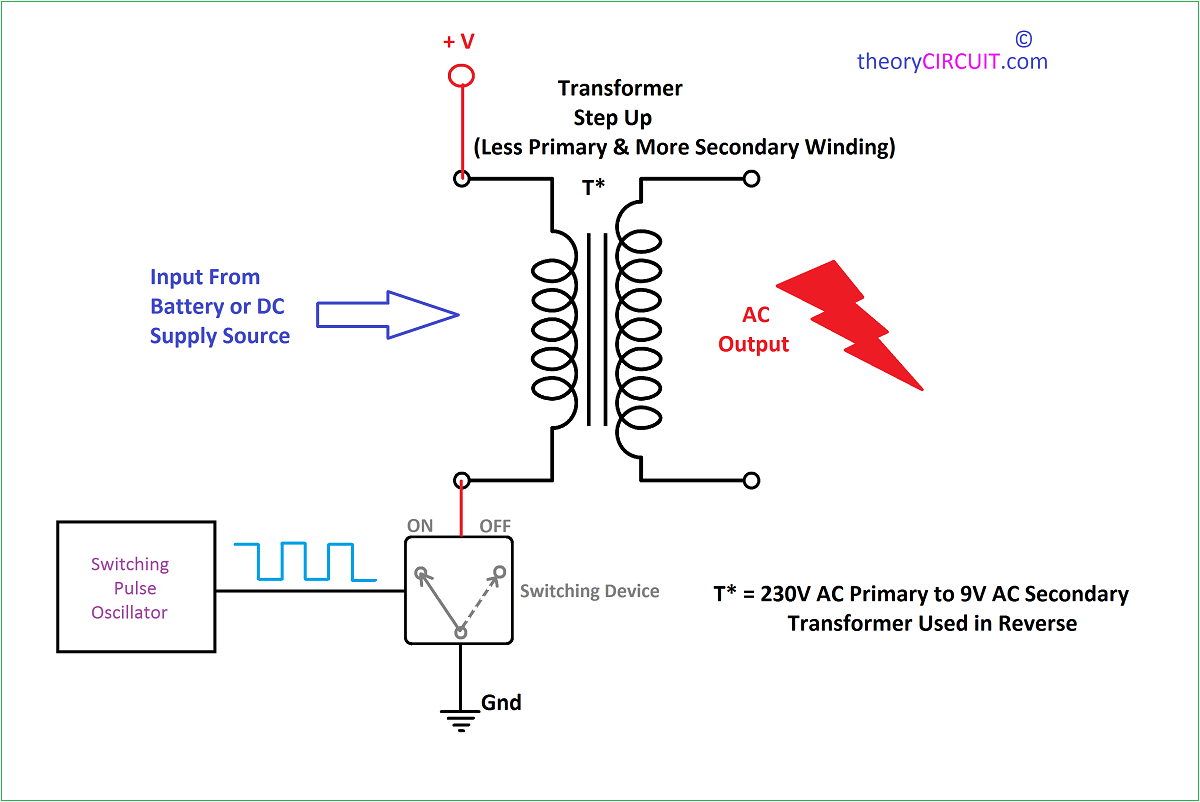
Lets consider the transformer with less primary and more secondary winding, for example 230V AC primary to 9V AC secondary used in reverse now less winding side becomes primary and more winding side becomes secondary. DC bias is applied in one terminal and -Ve or ground connected in another pin through switching device, when the switch is ON primary winding gets DC bias, when the switch is OFF primary winding disconnected from the DC bias, by the way 50Hz switching pulse drives the switching device so the winding gets discrete DC bias, magnetic flux produced from the primary winding induces more coil secondary so the high voltage EMF induced at secondary.
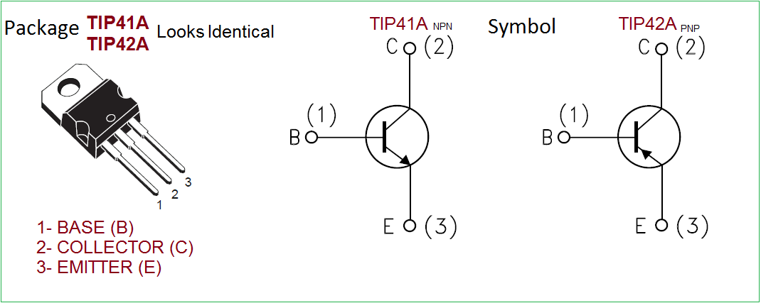
TIP41A / TIP42A Pinout
Similar Circuit
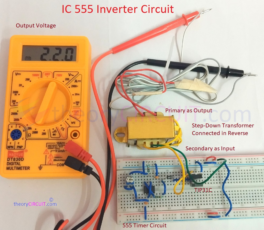
Simple Inverter circuit made by using IC 555 and Power Transistor TIP31C to bring 220V AC supply from 12V DC supply.
can you give an exemple for the frequency calculation please
Set the VR1 to 15 kilo ohms to get 60 Hz frequency.
With the value of 15 kilo ohm of VR1 you will get 56 – 58 Hz.
What do you mean with 1 to 1.5A transformer?
1 to 1.5 VA or sec Output over 1 Amp?
Jakob
can i use 15-0-15v 2amp transformer for this circuit
Will It work at 50hz?