
Last Updated on March 16, 2024
Simple LED flasher circuit can be designed by using timer IC 555, as we know the timer IC has internal voltage divider made by three 5KΩ Resistor hence the timer IC referred as 555. These devices are precision timing circuits capable of producing accurate time delays or oscillation. It can work in either monostable, Bistable or Astable mode, and then output frequency and duty cycles can be controlled by varying the value of external timing Resistor and Capacitor and also this timer IC available in different package.
IC555 can take input supply voltage from 4.5V to 16V and SE555 IC from Texas instruments can take maximum 18V. It will give TTL compatible output and up to 200mA current level. This timer IC being used in different types of applications from simple timing circuits to precision timing circuits.
IC 555 Pin configuration
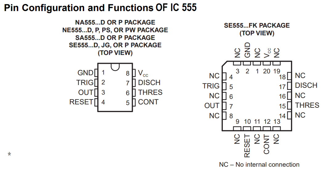
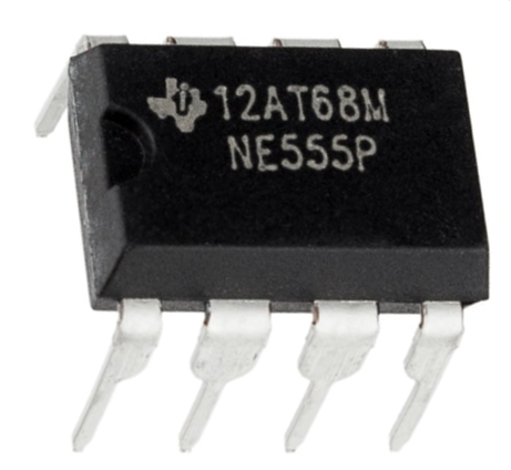
Two different package of IC 555 illustrated and both are works in the same way. Here 8 pin DIP or 8 pin SMD timer IC taken for testing the LED flasher circuit.
Pin 1: GND – Ground supply.
Pin 2: TRIG – Triggering input, start of timing input.
Pin 3: OUT – Timer output signal.
Pin 4: RESET – Active low Reset input forces output and discharge low.
Pin 5: CONT – Control voltage, Controls comparator thresholds.
Pin 6: THRES – Threshold end of timing input.
Pin 7: DISCH – Open collector output to discharge timing capacitor.
Pin 8: VCC – Input supply voltage 4.5V to 16V.
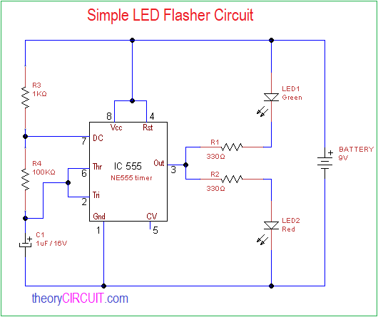
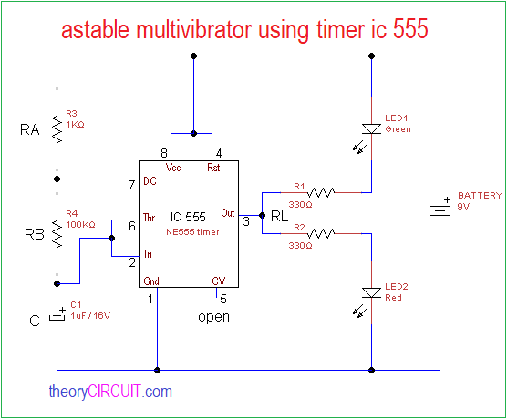
Circuit Diagram
LED Flasher Circuit Working!
Construction & Working
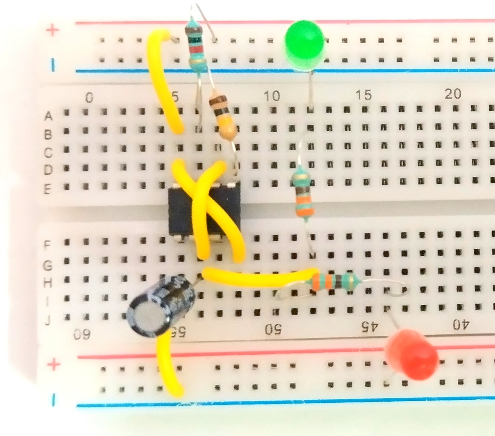
Here two LEDs are taken for flasher output and connected to the IC 555 output with different polarities hence the output positive pulse will derive LED2 and negative pulse drive LED1. Vcc and Reset pins are connected with positive Input power supply, hence no reset occurs during the oscillation.
Discharge pin is connected between timing Resistors R3 and R4, then tigger and threshold pin jointly connected between timing capacitor C1 and timing Resistor R4. Here control voltage pin 5 is being open and not connected with any bias.
Astable Multivibrator Operation
Output at the timer IC will be the square pulse and the ON duration, OFF duration of those pulses are decided by the Resistor RA, RB and Capacitor C. It can be mathematically derived by,
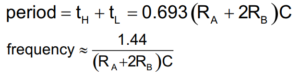
And also the output frequency is decided by the timing Resistors RA, RB and timing Capacitor C, by changing value of these elements we can get different range of output. When applying supply voltage after the wiring LED 1 and LED 2 starts blink alternatively.
It’s very simpal & good.
Give more simpal circuit?
Thanks for your Interest stay in touch 🙂