Last Updated on March 16, 2024
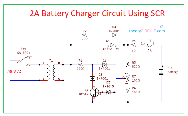
Simple 2A Battery charger circuit designed by using SCR (Silicon Controlled Rectifier) TYN612. Here the SCR acts as a Rectifying element and output DC Voltage Range can be controlled by varying R7 Resistor value. When the Target battery is low there is no potential flow to the base of BC547 transistor and transistor being in OFF state, hence the trigger voltage to the SCR reaches the Gate terminal and then SCR gets turned ON and gives rectified DC Voltage to the battery. When the target battery gets full charge or particular threshold charging level then Q2 transistor BC547 gets potential to the base through R5, R3 and R7 and so the Transistor gets turned ON and grounds the gate trigger voltage before reaching the SCR gate terminal and then SCR gets turned OFF and Charging supply to the battery blocked.
The AC source is given to the step down transformer which converts the large AC source in to limited AC source, filter the AC voltage and remove the noise and the given the voltage to the SCR where it will rectify the AC and give the resulting voltage to the battery for charging.
Circuit Diagram
BOM
| S no | DESIGNATOR | VALUE | QUANTITY |
| 1 | SPDT | 1 | |
| 2 | TRANSFORMER T1 | 1 | |
| 3 | R1 | 330Ω | 1 |
| R2 | 22Ω | 1 | |
| R3 | 820Ω | 1 | |
| R4,R7 | 100Ω | 2 | |
| R5 | 1Ω | 1 | |
| 4 | Q1 | TYN612 | 1 |
| Q2 | BC 547 | 1 | |
| 5 | D1,D2,D4 | 1N4001 | 3 |
| D3 | 1N1615 | 1 | |
| 6 | F1 | 2A | 1 |
| 7 | BATTERY | 1 |
Construction and Working
Here the Stepdown transformer used to step down 230 or 220V AC into 20V AC (use 2A or 3A transformer). SCR TYN612 Anode terminal connected to the secondary winding terminal hence it receives stepdown AC voltage and Converts in to DC Supply, this DC Voltage is used to charge the target battery.
In order to provide 2 Amps charging current there is no current limiting device after DC conversion. As we said simple 2A battery charger circuit, this schematic contains few easily available components and simple construction. Q1 SCR acts as a main rectifying element and Q2 transistor acts as gate trigger control switch and feedback circuit. Sensitivity level of Q2 transistor is depends on the R7 Variable resistor. Here D4 diode acts as a Reverse protection element. To avoid over current charging Fuse is added at the output line.
Note:- This circuit involves in handling of High AC and DC Voltage Handle with Extreme Care.
Can you give me the size of bobbin, the awg of coil to use in primary and secondary coil and how many turns of coil is need to get the exact output of stepdown power transformer which is 220acv to 20acV 2A? Hope you can provide an answer thanks
Hi Dodords
You can use any one of the 220VAc to 20Vac 2A transformer available in the market.
In that circuit we have used readymade stepdown transformer (230VAC to 20VAC / 2Amps).