Last Updated on March 16, 2024
Circuit diagram

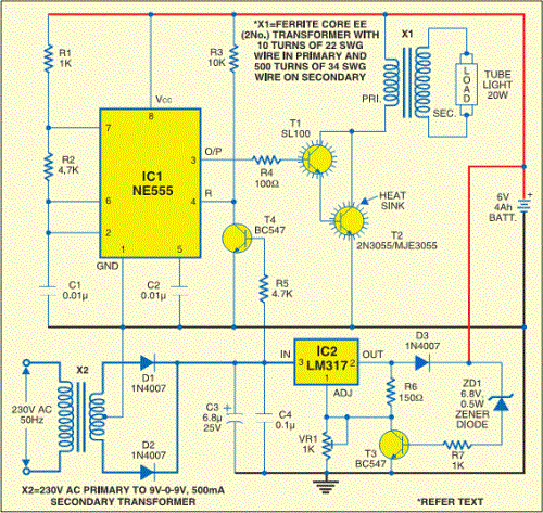
This full automatic emergency tube light circuit is a refer circuit from anonymous user. This circuit has two stages they are
- Battery charger circuit
- 20 Watts tube light driver circuit
The battery charger circuit is constructed by using step down transformer (9-0-9 V) center tapped, two 1N4007 diodes are acts as fullwave rectifier and rectifies the step downed AC supply from transformer this rectified DC is filtered and regulated by variable voltage regulator IC LM317 and then regulated constant DC supply is given to the 6 volt 4Ah battery.
Here the T4 transistor (BC547) splits the tube light driver circuit from charger circuit when the power supply present.
20 Watts tube light driver circuit is constructed with timer IC555 and step up transformer X1, this step up transformer X1 primary winding constructed with 10 turns of 22SWG and 500 turns of 34SWG wire on secondary, 20W tube light connected at the secondary of X1.
X1 transformer primary driven by pulse output from timer IC 555, pulse duration of IC555 decided by R1, R2 and C1 timing components.
[F = 1/T = 1.44/(R1 + 2R2).C1]
![]() Datasheet of IC LM317
Datasheet of IC LM317
Datasheet of IC LM555
