
Last Updated on March 16, 2024
Emergency light circuits are crucial for providing light during power outages or emergencies. We don’t need complicated design or schematic to design a Emergency light, here easy to construct 5 Simple Emergency Light Circuit given with construction and working details. Before getting into circuits lets understand the key components and functions of a typical emergency light circuit.
Power Source
Emergency lights usually operate on rechargeable batteries or Super capacitors. These batteries are charged when the main power supply is available and automatically take over during a power failure or outages.
Charging Circuit
The charging circuit ensures that the batteries remain charged when there is a power supply. It prevents overcharging, which could damage the batteries.
Inverter
In case of a power outage, the inverter converts the DC power from the batteries into AC power when we use AC light bulb as light source, In some circuit we can use LEDs as a light source and we don’t need inverter circuit part, some Voltage and current regulation only required.
Automatic Switching
The emergency circuit should have a mechanism for automatic switching between the main power and battery power. This ensures a seamless transition during power interruptions.
Duration of Operation
The circuit design should consider the required duration of operation during an emergency. This depends on factors such as the capacity of the batteries and the power consumption of the light source.
1. Emergency LED Lamp
Portable emergency LED lamp circuit with simple components and easy to make, here ten super flux white LEDs are used and this circuit powered by 4.5AH rechargeable lead acid battery.
Circuit Diagram
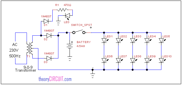
To construct this circuit choose 9-0-9v center tapped transformer and connect full wave rectifier circuit using two 1N4007 diodes. To indicate the power out from secondary winding of transformer an LED connected with half wave rectifier through 470Ω resistor. The DC supply from the full wave rectifier (D2 – D3) is directly applied to the rechargeable battery, a switch is used here to turn on and off the output LEDs, the LED1 – LED10 are super flux white LEDs hence it will produce more light intensity.
2. Emergency Tube light circuit
20 watts fluorescent emergency light is constructed with few simple components and 12 volt 7Ah battery.
Circuit Diagram
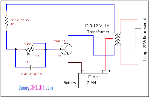
In this circuit (12-0-12V) step down transformer is utilized as the fluorescent driver transformer that is the primary winding terminal is connected to the 20 watts fluorescent light and secondary (12-0-12V) center tapped terminals are connected with switching pulse circuit. Here VR1 variable resistor and C1 capacitor is responsible for switching pulse that is applied to the switching power transistor Q1, 2N6101.(search in google to identify the pinout) This transistor connects and disconnects secondary winding of transformer with battery supply hence it produce EMF on winding this EMF increases in primary winding (step up) and the supply is enough to drive the 20 watts fluorescent light.
3. Emergency Light Circuit with White LED
Simple power efficient and easy to construct LED Emergency light circuit designed with few easily available components and it is very useful during power outage or instant light needs. LEDs used in this circuit are low current high brightness white LEDs hence it will glow longer time with minimum battery power. Some emergency light circuit utilizes fluorescent tube but that will consume more power and needs step up voltage from battery power. The following circuit utilize the direct supply from battery and doesn’t need step up voltage stage.
Circuit Diagram
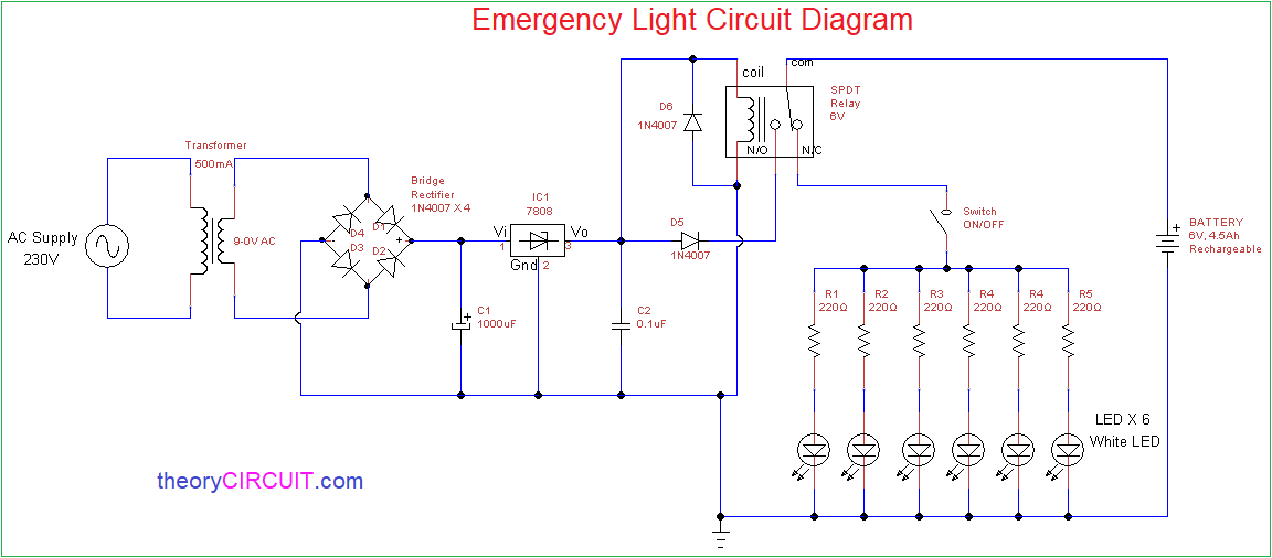
This circuit automatically turns on the LEDs when there is no AC power supply. A Rechargeable Battery (6V, 4.5Ah) connected in common with DC supply circuit and LED array circuit with the help of SPDT (Single pole double throw) Relay.
Here N/O (Normally Open) terminal of relay is connected with DC supply and N/C (Normally Close) terminal of relay is connected with LED array. The coil terminals of Relay is connected to the DC supply, during the input AC power supply presence common terminal of relay attracted to N/O and hence the Battery gets DC Supply for charging. When the absence of AC input supply Relay coil wont get DC supply and hence the common terminal attached with N/C so the battery supply flows through LED array and LED starts glowing.
Note:
- Use proper polarity of Rechargeable battery in this circuit.
- This circuit involves in handling of High Voltage AC supply, handle with extreme care.
- Use White LEDs for better light output.
4. Automatic LED emergency light circuit
Emergency lights are very crucial in some situations, the traditional emergency light uses fluorescent tube as light source hence it provides light upto maximum 2 hours to 3 hours. When we use white LEDs instead of fluorescent tubes it will give light upto 7 hours approximately.
Circuit Diagram
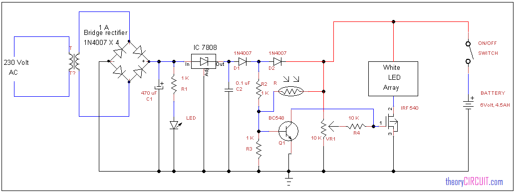
This circuit constructed with step down transformer (9-0-9V) and step downed AC voltage is rectified by the 1 Amps bridge rectifier (you can also use bridge rectifier module), the LED connected with resistor R1 gives status about output DC voltage from bridge rectifier. By using positive regulator IC 7808 the DC voltage is regulated and this regulated supply fed into light sensing circuit. The light sensing circuit detects the light by using normal 5mm LDR, this LDR provides low resistance when feels light and gives high resistance to the supply flow when feels dark condition sensing level of LDR can be varied by VR1 10KΩ variable resistor.
During the day light time LDR allows supply through it to the Q1 transistor base hence the Q1 transistor turn ON and connect MOSFET gate terminal to the ground so the LED array disconnected from DC bias ground supply. When dark condition arrives the LDR blocks current flow through it so the Q1 transistor base receives minimum voltage that is not turn ON the transistor. Hence the Q1 transistor remains in OFF condition there is no current flow between collector and emitter that is emitter open. No voltage is received at gate terminal of MOSFET hence the current flow occurs between drain and source terminals, so that LED array glows, the battery (6 volt, 4.5Ah) is connected across the bias when the power failure occurs this battery provides power supply to the circuit.
5. USB Rechargeable LED Circuit
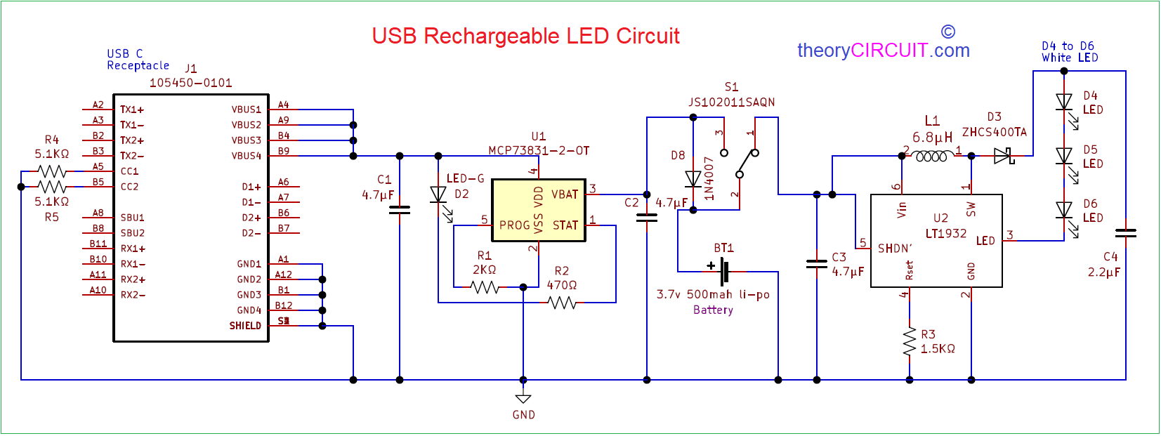
USB Rechargeable LED circuit designed for longer glowing time. This circuit has USB C Receptacle hence we can charge this circuit battery easily. LiPo (Lithium polymer) 3.7V, 500mAH battery used in this prototype circuit, you can use lower current rating Li-Po battery also. We can directly remove and connect LiPo battery with this circuit through JST connector. This USB Rechargeable LED circuit has three white LEDs, due to the low power LEDs consumption this circuit gives longer duration glowing time. Hence it can be used as Rechargeable LED mini emergency light circuit.
Circuit Diagram
https://theorycircuit.com/usb-rechargeable-led-circuit/
This circuit has Regulator & charger section, then battery and then LED driver section. Power supply is taken from the USB C connector VBus and GND terminals and then IC MCP73831/2 miniature single cell fully integrated li-Ion, li-Polymer charge management controller Regulates the power supply and gives output voltage as 4V and output current as 500mA, you can program this IC to give different range of output current by changing Resistor value at PROG pin, refer data sheet for more details.
A slide switch S1 (SPDT SMD) connects battery with LED driver circuit section. Through this switch power supply flows to the LED driver IC LT1932, it is a constant current DC / DC LED driver in thin SOT package. It drives the output white LED devices. If you need high luminance then choose high power white LEDs, don’t forget to change the footprint in PCB files and bill of materials.
Hope these five emergency light circuit helps you to build your own emergency light.
Discover five straightforward emergency light circuits that enhance safety. Illuminate your space with these simple yet effective DIY solutions