Last Updated on March 16, 2024
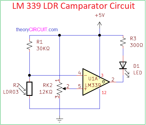
Simple LDR Comparator Circuit designed by using IC LM339 from Texas Instruments. Which is a Quad comparator IC, only one of the 4-bit internal comparators of this IC is used in this circuit. This circuit operates with 5 Volt Regulated DC supply.
Here the light sensing component of this circuit is a Light Detecting Resistor or LDR. This is just a photo-sensitive component that change its resistance according to the light shining on it. The more light that shines on it, the lower is its Resistance.
Circuit Diagram
BOM
| S.no | Designator | Value | Quantity |
| 1 | U1A | LM 339 | 1 |
| 2 | R1 | 30K | 1 |
| Variable Resistor R2 | 12K | 1 | |
| R3 | 300 | 1 | |
| 3 | LDR | 1 | |
| 5 | LED | 1 |
Construction and Working
In above circuit we have connected pin 4 to LDR and R1 resistor act as a voltage divider circuit. Which is inverting terminal when light hits LDR sensor the resistivity through it pin will be lowered and voltage will get high on the pin 4 which results as low output at pin 3.
We added the variable resistor at pin 5. As the variable resistor is set for low resistance, the voltage on pin 5 gets high. The inverting terminal pin 4 requires low input signal to stay below the voltage on pin 4 for higher output which means it is set for low intensity on light. The more light shining on the LDR, the lower is its resistance and the higher is the voltage at this output. The comparator output changes state every time the voltage at the inverting input exceeds or falls below the threshold voltage set at the non-Inverting input. LED ON when LDR is in the dark. We can use Relay or Buzzer instead of LED to get this circuit into specific application.