
Last Updated on March 16, 2024
Automatic Fan Speed Control Circuit Arduino LM35 Programming is very easy to experiment and it can be used to control any target device with relay depends on temperature level. For temperature measurement here we use LM35, this is precision integrated circuit temperature devices with an output voltage linearly proportional to the Centigrade temperature. Due to its output characteristics we don’t need to take kelvin in output value calculation. This LM35 temperature sensor works without any external components, it just need 4 V to 30 V Regulated DC supply as bias. In this circuit we use +5V DC from Arduino development board. This sensor gives temperature output with accuracies of ±1/4 °C at room temperature and ±3/4°C over a full −55°C to 150°C temperature range.
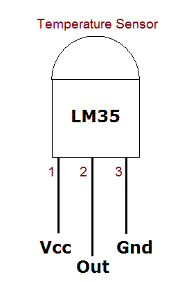
As this LM35 gives analog output (Linear + 10-mV/°C Scale Factor), we can directly connect output pin of LM35 to any Analog input pin of Arduino board. LM35 is can operate with single power supply or dual power supply and consumes only 60 μA for its own operation. It comes in different packages like TO-CAN (3), TO-92 (3). Here we used LM35 TO-92 from Texas Instruments.
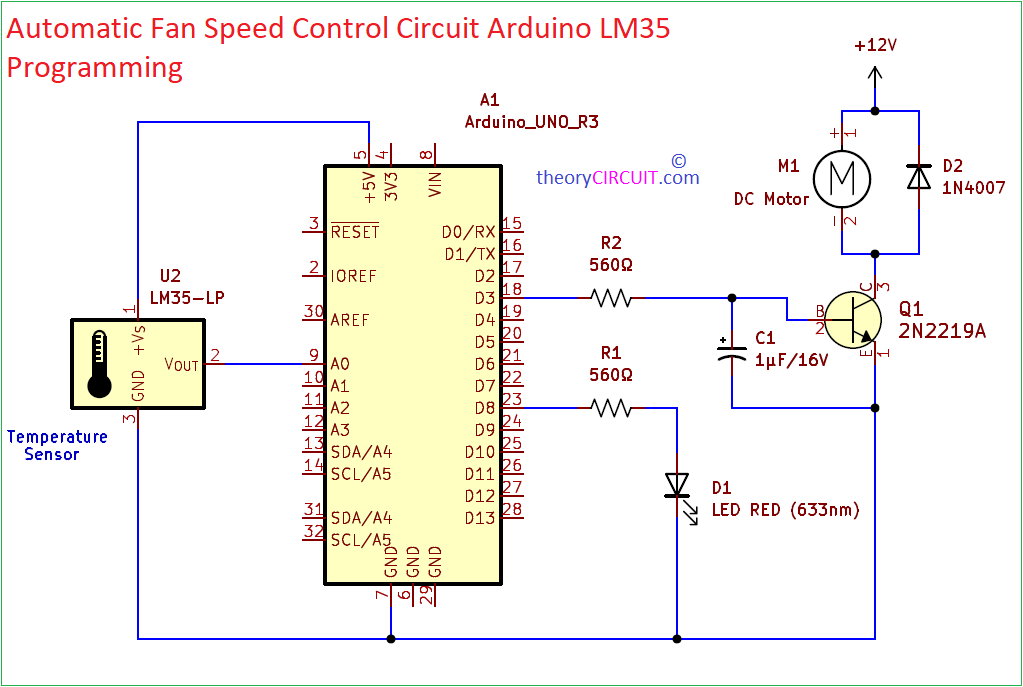
Circuit Diagram For DC Fan Control
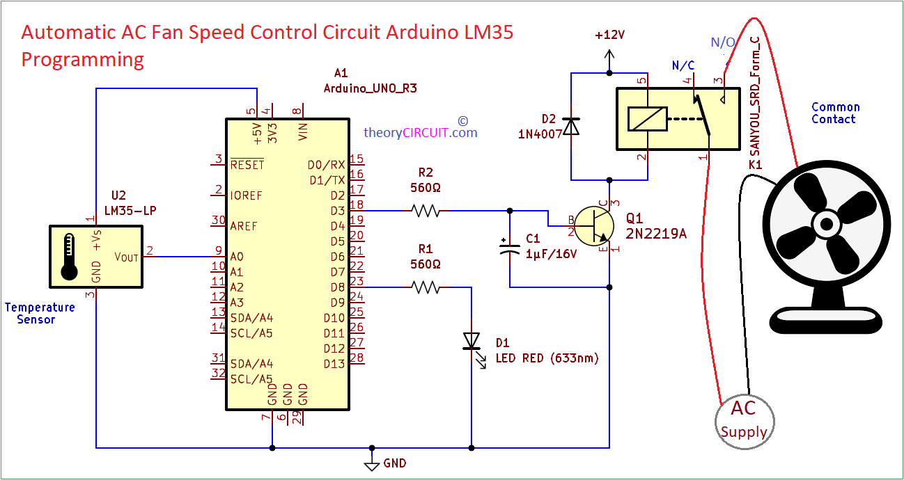
Circuit Diagram For Relay (AC Fan) Control
Components List
- Arduino Uno board = 1
- Temperature Sensor LM35 = 1
- LED RED 5mm = 1
- Resistor 560Ω = 2
- Capacitor 1μ/16V = 1
- Transistor 2N2219A = 1
- Diode 1N4007 = 1
- 12V DC Fan = 1
- Sanyou SRD relay = 1
Construction & Working
This circuit can be constructed in either bread board or common PCB board, have additional DC power source 12V for fan or Relay. As previously said LM35 only needs 5V hence 5V pin and Gnd pin of Arduino connected with LM35 and output pin is directly connected to Analog input pin A0 and mentioned in the following program. Indication LED is connected with Digital pin D8 and declared as output pin. D3 PWM pin is declared as output pin and connected to the base of switching transistor 2N2219A. Here we have to change the output pulse width depends on the temperature level sensed by the LM35. By the way we can achieve different speed level. Whenever the temperature sensor detects the changes in temperature outside the Arduino varies the PWM output at D3 pin hence the speed of fan varies.
For to control Relay, use D3 pin as a Digital Output pin and declare it on Arduino code. In this way we can only turn ON and OFF the AC fan depends on the temperature level. Use any target load to ON and OFF based on temperature level. Whenever the temperature sensor detects the changes in temperature above 30°C then Arduino varies the digital output (HIGH) at D3 pin hence the speed of fan varies. Below 25°C the digital output becomes (LOW) at D3 pin.
“This Circuit involves in Handling of High Volt AC supply it might Dangerous if it is not Handled properly. Handle with Extreme Care.”
Automatic Fan Speed Control Circuit Arduino LM35 Programming
int tempPin = A0;   // connect Sensor output pin
int fan = 3;       // Output drive for fan
int led = 8;        // fan status led pin
int temp;
int tempMin = 25;   // Minimum temperature to start the fan
int tempMax = 75;   // Maximum temperature to turn fan at 100% speed
int fanSpeed;

void setup() {
  pinMode(fan, OUTPUT);
  pinMode(led, OUTPUT);
  pinMode(tempPin, INPUT);
  Serial.begin(9600);  // Initialize serial communication at 9600 baud rate
}

void loop() {
   temp = readTemp();     // read temperature
   Serial.print("Temperature: ");
   Serial.print(temp);
   Serial.println(" °C");

   if(temp < tempMin) {   // if temp is lower than minimum temperature
       fanSpeed = 0;      // fan is off
       digitalWrite(fan, LOW);
       Serial.println("Fan Speed: OFF");
   }
   if((temp >= tempMin) && (temp <= tempMax)) {  // if temperature is higher than minimum temperature
       fanSpeed = map(temp, tempMin, tempMax, 32, 255);
       analogWrite(fan, fanSpeed);  // spin the fan at the fanSpeed speed
       Serial.print("Fan Speed: ");
       Serial.println(fanSpeed);
   }

   if(temp > tempMax) {        // if temp is higher than tempMax
     digitalWrite(led, HIGH);  // turn on led
     Serial.println("Fan Status: Overheating!");
   } else {                    // else turn off led
     digitalWrite(led, LOW);
     Serial.println("Fan Status: Normal");
   }
   delay(1000); // Delay for 1 second before reading temperature again
 }

int readTemp() {  // get temperature and convert it to celsius
  temp = analogRead(tempPin);
  return temp * 0.48828125;
}
Automatic Relay Control Circuit Arduino LM35 Programming
const int tempPin = A0;    // LM35 temperature sensor connected to analog pin A0
const int relayPin = 3;    // Relay control pin connected to digital pin 2

const int tempThresholdHigh = 30;  // Temperature threshold to turn on the relay (in Celsius)
const int tempThresholdLow = 25;   // Temperature threshold to turn off the relay (in Celsius)

void setup() {
  pinMode(tempPin, INPUT);
  pinMode(relayPin, OUTPUT);
  digitalWrite(relayPin, LOW);  // Ensure the relay is initially off
  Serial.begin(9600);
}

void loop() {
  int tempValue = analogRead(tempPin);  // Read temperature value from LM35 sensor
  float temperature = (tempValue * 0.48828125);  // Convert analog reading to Celsius

  Serial.print("Temperature: ");
  Serial.print(temperature);
  Serial.println(" °C");

  // Check temperature and control the relay
  if (temperature >= tempThresholdHigh) {
    digitalWrite(relayPin, HIGH);  // Turn on the relay
    Serial.println("Relay Status: ON");
  } else if (temperature <= tempThresholdLow) {
    digitalWrite(relayPin, LOW);  // Turn off the relay
    Serial.println("Relay Status: OFF");
  }

  delay(1000);  // Delay for 1 second before reading temperature again
}
In above two program we use the following method to translate analog output voltage from LM35 to Degree Celsius
int readTemp() {
temp = analogRead(tempPin);
return temp * 0.48828125;
}
Transistor 2N2219A Pinout
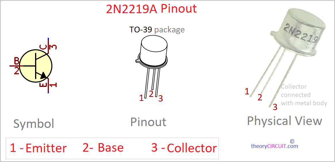
2N2219A is a NPN Switching Silicon Transistor. This is widely used for High frequency Switching Applications. It have good power handling capacity with maximum collector current (IC) around 800 mA, Collector to base Voltage (VCB) of 75V and Collector to Emitter Voltage (VCE) of 40V. This device comes in TO-39 metal can package.
SANYOU SRD Relay Pinout
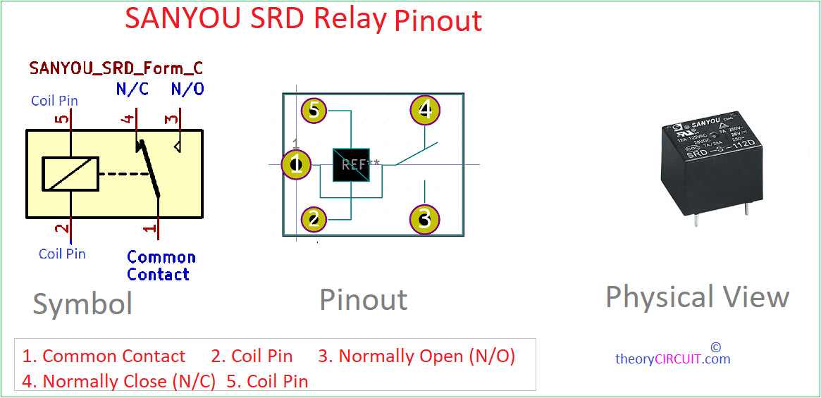
Sanyou SRD Relay is commonly used SPDT (Single Pole Double Throw) Relay. It is available in different Coil Voltage levels from 3V to 48V. Here we have used 12V Relay SRD-112DM. Due to its ultra miniature size and high contact capacity (up to 12A) it is used in different Electronics applications. The relay operates on the principle of electromagnetism, allowing it to control high-power electrical circuits with a low-power input signal. The Sanyou SRD relay is known for its low power consumption, fast response times, and excellent electrical isolation between the input and output circuits.