
Last Updated on March 16, 2024
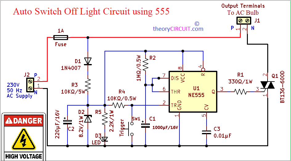
This Auto Switch Off Light Circuit using 555 timer designed to turn ON a light bulb and automatically turn OFF after 15 Minutes without turn off the switch. It can be used in many applications like, stair case, garage door, Security lighting etc.., This circuit uses Direct AC (220V – 230V) supply for its operation and controls the AC bulb.
This Circuit Involves in Handling of High Voltage AC supply and it is Highly Dangerous, Handle with Extreme care and This Circuit is Recommended for only Experienced.
This circuit converts input AC supply into DC for its own operation power supply, proper earthing is required due its non isolation characteristics. This simple circuit employs timer IC 555 in a monostable or one shot pulse generator configuration. When ever we give trigger by pressing SW1 the timer generates approximately 15 Minutes pulse and makes turn ON the load through Triac BT136. Use Monostable Multivibrator Calculator to Calculate the Pulse Duration.
Circuit Diagram
Components List
- Timer IC 555
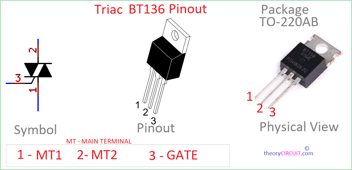
- Triac BT136
- Tactile push button switch (SW1)
- Zener diode 8.2V/1W
- Diode 1N4007
- Class fulse 1A with holder
- 2 pin Screw terminal
- Resistor 10KΩ/5W
- Resistor 2.2KΩ/1W , 330Ω/1W
- Resistor 10KΩ/0.5W, 1MΩ/0.5W
- Capacitor 220μF/16V, 1000μF/16V, 0.01μF (disc)
Construction & Working
As previously said this circuit is configured in monostable or one pulse generator mode. Here diode D1 Converts AC Supply into DC as a Halfwave rectifier and R3 Limits the current flow. Zener Diode D2 Regulates the DC supply into 8 V DC. Then this regulated DC supply is applied to the timer IC remaining circuit as a bias. LED D3 indicates the power supply presence. For 555 timer, Resistor R2 and Capacitor C1 acts as timing elements. Output pulse duration is depends on these element values.
The capacitor C1 charges through the resistor R2 towards the voltage level of the power supply. The voltage across the capacitor rises exponentially, following the typical charging curve. During this time period output of Timer 555 will be logic HIGH state. The BT136 Triac Receives enough Gate signal to conduct supply through MT1 and MT2, hence the load bulb start to glow.
When the voltage across the capacitor reaches a threshold level, about 2/3 of the supply voltage, the internal comparator of the 555 timer detects this and triggers the circuit to revert to its stable state that is LOW. Here BT136 don’t receive enough Gate signal so it comes to OFF state and there is no conduction between MT1 and MT2, hence the light bulb comes to OFF. In this stable state, the output at pin 3 switches back to a low logic level. The capacitor then begins to discharge through the same resistor until its voltage drops below one-third of the supply voltage. At this point, the circuit is ready for the next trigger event.
Triac BT136 Pinout
Your last paragraph is totally wrong. When the switch is pressed, pin 2 (TRG) goes low, this sets the latch inside the 555, what turns pin3 high, activating the Triac. At the same time, pin7 goes high impedance, allowing the capacitor C1 to start charging via the resistor R2 (up to this point C1 was discharged and grounded via Pin7). When C2 reaches 2/3 VCC, the 555 pin 6 senses such voltage, flips the latch, lower the output, disable the Triac, activates pin7 low, discharges C2 at once, and pin7 stays like that shorted to ground until a new press on switch is make. You said the capacitor discharges via the resistor, that is false. The problem with this circuit is that after few cycles the 555 will blow up, pin7 internal transistor cannot sustain to discharge C2 1000uF in a fast pulse inrush like that, it needs a resistor in series with pin7, value from 50 to 100 ohms, to avoid the inrush current and limit the discharge C2 current.