
Last Updated on April 1, 2024
Measuring Frequency of a signal is an important task in many electronic product development and applications. We often use Oscilloscope to measure signal frequency or use frequency counter device, both are bulky and not suitable for continuous measurement and indications, they are pricey too. That’s why theorycircuit brings you simple Pulse Frequency Counter using Raspberry pi Pico. It can be used to count the input pulse frequency in Hz. If you want to use it for other signals like sine wave, triangle wave then use Schmitt trigger circuit to convert those signals into corresponding square pulse.
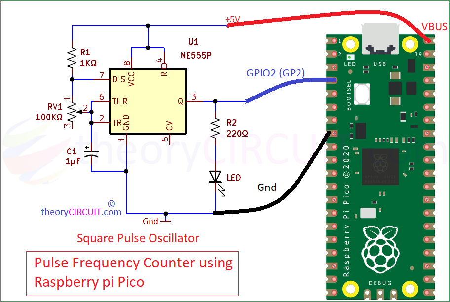
In this project we used Timer IC 555 to produce Square pulse signal in Astable multivibrator mode, Either you use standalone circuit or external signal source remember to make common Ground (Gnd) connection between Raspberry pi Pico board and Signal source. Then only it works properly.
If you are new to Raspberry pi Pico then read, Easy Way to Code Pico Board.
Schematic Diagram
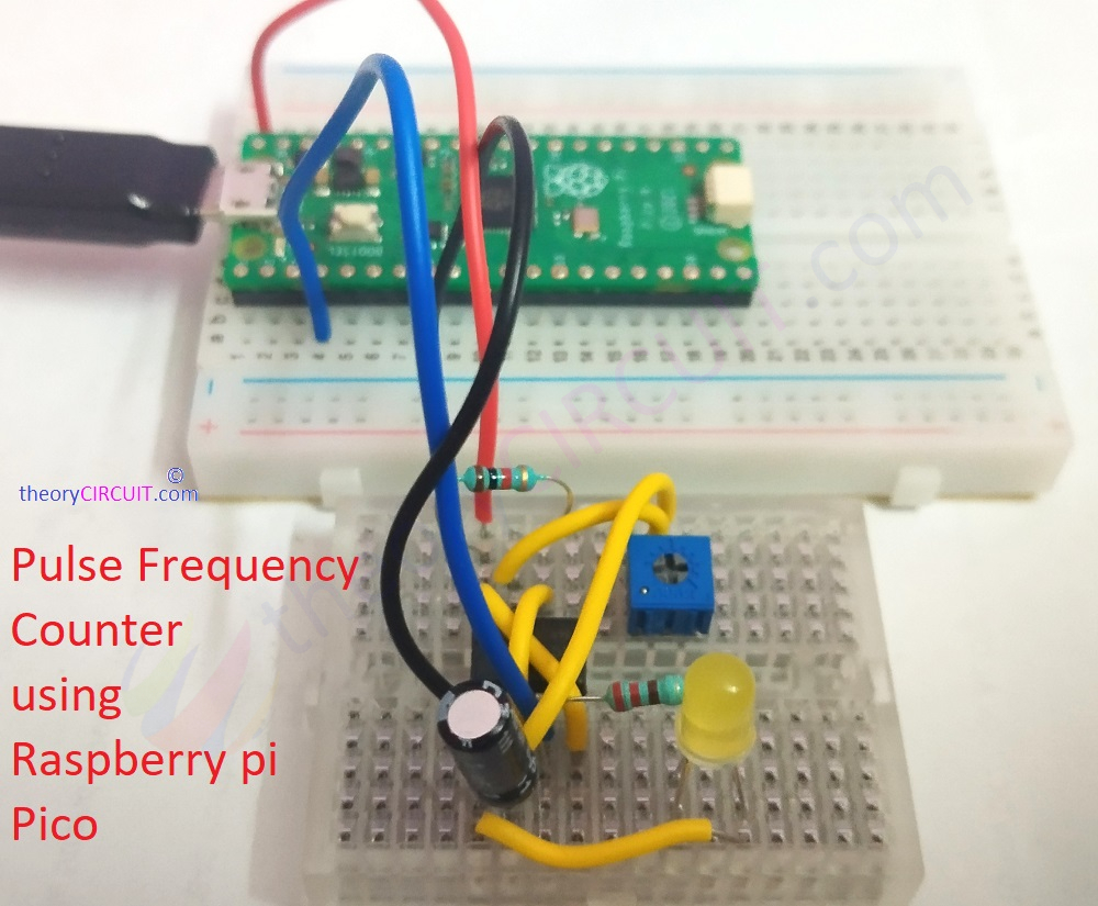
Wiring
Components Required
- Raspberry pi Pico board
- Hookup wires
- USB Cable (micro B)
- Computer with Thonny IDE
If you have external Signal source then following Components are not required.
- Timer IC 555
- Resistor 1KΩ, 220Ω each one
- Variable Resistor 100KΩ
- Capacitor 1μF
- LED
- Breadboard
- Connecting Wires
Working Video
Construction & Working
As previously said, we used IC 555 Timer Astable multivibrator circuit biased with VBUS (5V) and Gnd from pico board. It produce square pulse depends on the timing Resistor RV1 and Timing Capaciot C1. By varying the RV1 we can get different frequency range pulse output. For indication of output pulse we used an LED at the ouptut of timer IC. This Output from Pin 3 of IC555 is directly connected to the GPIO pin GP2. The following microPython code gives output in shell and graph, you can use LCD for stand alone frequency measurement projects.
How to Calculate Frequency?
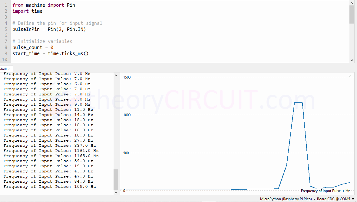
The following code utilizes an interrupt handler to count the number of pulses received on the Input Pin GP2. Count Pulse fuction increase pulse count for every rising edge detected on the input pin.
The ‘time.ticks_ms()’ function keeps track of the time, which returns the number of milliseconds since the board started running. and the ‘Start_time’ variable stores the time at the begining of each one second interval.
After every second the frequency is calculated as, frequency = pulse_count / 1.0 # Pulse count divided by time in one second, after that calculated frequency printed in shell as Hz.
microPython Code for Frequency counting
Screenshot
This is a great bit of code, I spent ages with Chat GPT to develop a tone detector for 1750 Hz. this code was great and just worked first time.
Alan
Thanks for sharing this application! I easily adapted your code to measure rpm of a motor shaft. Everything works great until the frequency being measured exceeds about 38kHz; beyond that, the measured value starts to drop off. I’ve removed most non-essential code from within the “While True” loop, but the problem persists. I need to measure up to 210 kHz for a 0-3500 rpm machine shaft.
Any suggestions? What is the maximum frequency you’ve been able to measure?
I’m guessing I’ll need a faster processor and/or a more efficient language, but perhaps I’m overlooking something…
FYI, I am running a Pico 2 W.
Your predicted numbers seem a bit off. Let’s think about this. 210 kHz means 210000 cycles per second or revolutions per second. To convert Hz to RPM we would further multiply this by 60 s, giving a brain melting speed of 12.6 Million RPM! This is in the RF and no motor spins as fast as this. A motor with an armature 2cm in diameter would have its surface moving ~4% the speed of light! If your maximum target frequency is 3500 RPM then that translates to 3500/60=~58.3 Hz. This is considerably easier to measure. I hope that helps.