Last Updated on March 16, 2024
Wireless LED Light Array Circuit designed by using most famous timer IC 555 and it is very easy to construct. This circuit will help you to experiment wireless power Transmitter and Receiver. This circuit uses Insulated Copper coil to convert high frequency Square pulse to electromagnetic flux and also to receive it. In recent time Wireless power transmission Technics are widely used in different electronic applications. You may heard of wireless mobile charger, wireless gadget charger, Inductive coupling, RFID tags, Induction cooking and continuous wireless power transfer in implantable medical devices. Here we are looking into the basic needs and an exciting experiment to understand the operation of wireless power transmitter and receiver.
We know that current flow through a coil will make electromagnetic flux and a moving electromagnetic flux will induce current flow through wire. This is the basic concept used in almost every Wireless power devices. Here we have taken 12 white LEDs and trying to make it glow wirelessly.
Copper Coil Setup
Insulated copper wire with 18 SWG winded 25 turns and used as Power Transmitter coil, this coil will make strong electromagnetic flux by using high frequency square pulse from timer IC 555. Receiver Coil made with 22 SWG insulated copper wire and winded 100 turns, this coil will make current flow and potential difference depends on the received electromagnetic fields.
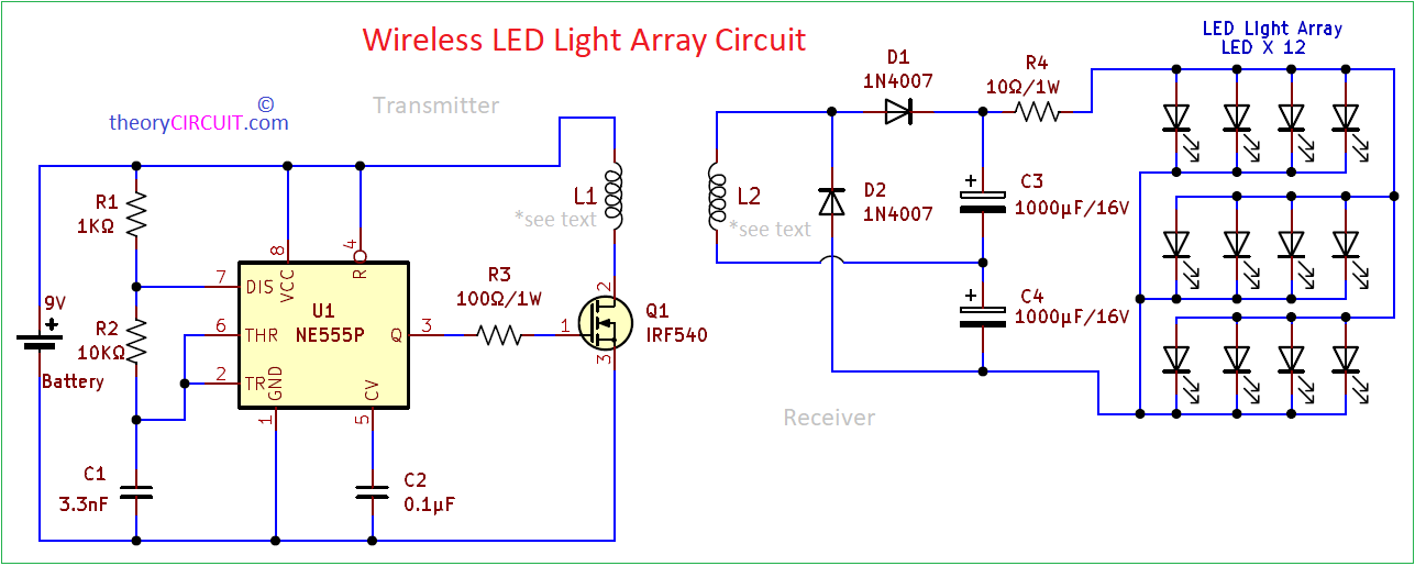
Circuit Diagram
Components List
- Timer IC NE555P
- IRF540 Power MOSFET
- Insulated Copper Wire 18 SWG
- Insulated Copper Wire 22 SWG
- Resistor 1KΩ, 10KΩ, 10Ω/1W, 10Ω/1W
- Capacitor 3.3nF, 0.1μF
- Electrolytic Capacitor 1000μF/16 = 2
- Diode 1N4007 = 2
- White LED = 12 (any color)
- 9V Battery
Construction & Working
Transmitter Circuit
Wireless power Transmitter circuit is Constructed by using Timer IC 555 in Astable Multivibrator Configuration to Produce 20KHz Square pulse. Here the timing components (Resistors) R1, R2 and (Capacitor) C1, gets charging and discharging continuously and creates continuous cycle of oscillation. Here VCC pin and Reset pin connected with positive supply, R1 resistor is connect between Discharge pin and positive supply, R2 resistor is connected between discharge pin and Shorted Threshold, Trigger pin. C Capacitor is connected between (THR, TR) pin and GND.
The capacitor C1 begins to charge through Resistor R1 then Discharge pin 7 and R2, as the voltage across the capacitor reaches 2/3 of the Power supply (VCC) then the internal flip flop of the 555 timer changes its state, this causes the discharge pin 7 to go LOW and then the Capacitor C starts to discharge through Resistor R2 and the discharge pin 7. When the voltage across the capacitor decreases to 1/3 of power supply (VCC) then the internal flip flop changes its state again and the Discharge pin 7 goes HIGH, this cycle of charging and discharging repeats and generates Continuous Square pulse at output pin.
MOSFET IRF540
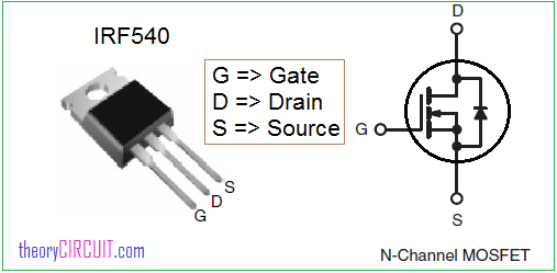
IRF540 N-Channel MOSFET receives square pulse in Gate terminal and acts as Switch, that is it turn ON during positive pulse and turn OFF during negative pulse. Hence Coil L1 Connected with Drain terminal gets discrete (ON and OFF) supply, and produce strong fluctuating electromagnetic field.
Receiver Circuit
Receiver circuit starts with Copper coil L2, this will convert fluctuating electromagnetic field into flowing current and Voltage Doubler increases the potential difference enough to drive 12 LEDs. The diode D1 acts as rectifier and converts pulsating AC into DC. Check the output voltage and current before placing LEDs in the Receiver circuit. Some times high voltage (>4V) will damage the LED. Distance between the Transmitter and Receiver coil plays important roll in output voltage. If you are receiving high voltage than required level then you can introduce voltage regulator at the output side.